Image to 3D Model AI: OpenGL Vs DirectX Normal Maps
Learn how OpenGL and DirectX normal maps differ, which green channel your workflow needs, and how to fix lighting errors with image to 3d model ai.
If an image to 3d model ai workflow includes normal maps, choosing the wrong green-channel convention can make surface lighting look inverted. This guide explains which format to use in common 3D tools and how to correct a mismatch.
OpenGL and DirectX normal maps contain the same surface information, but they disagree about the direction stored in the green channel. This guide matches the correct convention to common engines and shows how to diagnose the upside-down lighting that appears when the choice is wrong.
The fix is usually one setting, not a new texture: choose OpenGL or DirectX in the normal map generator, then check the result under a moving light before downloading the maps.
The short version
- Choose OpenGL for Blender, Unity, Godot, glTF, GLB and three.js.
- Choose DirectX for Unreal Engine and 3ds Max.
- The difference is the green channel: OpenGL uses Y+, while DirectX uses Y−.
- If bumps look like dents or cracks catch light from the wrong side, switch the convention or flip green on import.
What the green channel actually does
A normal map stores the direction a surface is facing at each pixel. It is not a color image in the artistic sense, even though it is displayed as red, green and blue. The red and green channels describe the surface slope across the texture, while blue represents the part facing outward.
The disagreement between OpenGL and DirectX is limited to the vertical direction:
- OpenGL stores the green direction as Y+, or up.
- DirectX stores the green direction as Y−, or down.
The red direction stays the same. The blue direction stays the same. To convert between the conventions, flip the green channel and leave the other channels untouched.
That is why a normal map can look correct in one application and wrong in another without any change to the mesh, UVs or source photo. The pixels contain valid surface directions, but the receiving program interprets the vertical component using the other convention.
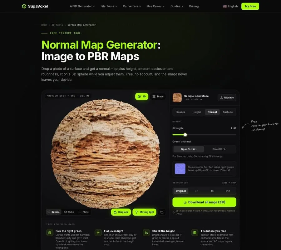
The Normal Map Generator exposes the OpenGL or DirectX choice directly in the Normal settings.
Which convention does your engine need?
Use this mapping when exporting a tangent-space normal map:
- Blender — OpenGL
- Unity — OpenGL
- Godot — OpenGL
- glTF and GLB — OpenGL
- three.js — OpenGL
- Unreal Engine — DirectX
- 3ds Max — DirectX
The important detail is that the convention belongs to the material pipeline, not to the photograph. A stone image does not inherently have an OpenGL or DirectX normal map. The same height information can produce either version by changing the green channel.
Unity is a common source of confusion because Unity projects may use assets created for several different tools. For a GLB material, use OpenGL normals when preparing the texture. The unity 3d models guide also covers the GLB import path through glTFast and the way Unity creates materials from the file.
Unity uses the OpenGL Y+ convention for tangent-space normal maps.
Unreal Engine uses the DirectX convention. If a material imported from another tool looks inverted, the normal texture is a likely place to check before changing lights or rebuilding the mesh. The unreal engine 3d models guide explains how GLB files enter Unreal through Interchange and become static meshes with materials.
Unreal Engine expects the DirectX Y− convention for the green channel.
How to choose the setting before export
A reliable workflow is simple:
- Identify the application that will display the material.
- Select OpenGL or DirectX according to the engine list.
- Inspect the preview with a moving light.
- Export the normal map at the same resolution as the rest of the material set.
- Test the texture on the actual mesh or a representative sphere.
In the browser tool, the Green channel control is on the Normal tab. OpenGL is the default. Switch to DirectX when the destination is Unreal Engine or 3ds Max.
The generator computes normal, height, ambient occlusion and roughness maps from the same height field, so the maps line up pixel for pixel. That matters when diagnosing a material: if the normal map looks wrong but the height preview looks sensible, the channel convention is a better suspect than a mismatch between separately prepared images.
The tool can download the whole set as a ZIP, or individual maps from the Maps view. For normal maps, use the selected OpenGL or DirectX version and keep the height map available for comparison.
Recognizing an inverted normal map
An incorrect green convention produces a distinctive lighting error. The surface may still appear detailed, but the relief reads backward.
Look for these symptoms:
- Raised bumps appear to sink into the surface.
- Recesses catch highlights as if they were ridges.
- A light moving across the material makes the relief change in the wrong direction.
- The texture looks acceptable under one light angle but obviously inverted under another.
- Small grooves appear to project outward instead of cutting inward.
A normal map that is merely too strong looks exaggerated but remains directionally consistent. An inverted map changes the direction of the vertical slope. That distinction helps separate a strength problem from a channel problem.
The quickest test is to switch between OpenGL and DirectX and compare the sphere preview. If the relief changes from inside out to correct, the convention was wrong for the destination application. If the preview still looks wrong in both modes, inspect the source image and height settings instead.
Fixing the problem in the right place
There are two valid places to correct the convention.
Fix it during generation
Select the required Green channel option and download the map again. This is the cleanest approach when the texture will be shared with a team or moved between applications, because the file itself matches its intended destination.
Flip green during import
Many material systems provide a setting that inverts the green channel. Use that when the normal map is already stored in the other convention or when a shared asset must serve different renderers.
Do not flip green and also switch the generator to the other convention unless the two operations are intentional. Applying both corrections returns the map to its original interpretation.
Keep the texture marked as non-color or linear data in the material. A normal map describes directions, so applying color-management adjustments can distort those values even when the green convention is correct. The base color belongs in sRGB; normal and roughness data do not.
When the source photo is the real problem
A green-channel mismatch is not the only reason a normal map can look backward. The generator assumes that brighter parts of the image are raised and darker parts are recessed. That works well for stone, bark, concrete and gravel photographed in even light. It fails when brightness comes from paint, color variation or hard shadows rather than physical relief.
Pale mortar between dark bricks is a useful example. The mortar may be brighter in the photo but lower than the bricks. In that case, use Invert on the Height tab rather than changing OpenGL to DirectX. The two settings solve different problems:
- Green-channel switch — changes the vertical direction convention for the target application.
- Height inversion — reverses which brightness values are treated as raised or recessed.
Hard shadows can also become false cavities. A dark cast shadow may be interpreted as a deep groove, and a bright reflection may become a raised ridge. Check the height interpretation in the preview before blaming the normal convention.
For materials that will repeat, prepare the source image first with a seamless texture generator. A tileable color image gives the normal generator continuous edges to work from, and its filters wrap around the edges when the input is seamless. That keeps the normal, ambient occlusion and roughness maps aligned at the tile boundary.
A practical troubleshooting sequence
When a material looks inverted, check in this order:
- Confirm the target application’s convention.
- Check whether the generator is set to OpenGL or DirectX.
- If the map came from elsewhere, inspect whether the importer flips green.
- Look at the preview under moving light.
- Check whether bright areas in the source photo are actually raised.
- Use Height inversion only if the physical relief is reversed.
- Verify that the normal texture is imported as linear or non-color data.
This order avoids rebuilding a mesh when the issue is only one channel. It also avoids changing the green channel when the source photograph has misleading lighting.
FAQ
Is OpenGL better than DirectX for normal maps?
Neither is better. They encode the same normal directions with opposite signs in the green channel. Choose OpenGL for Blender, Unity, Godot, glTF and three.js, and DirectX for Unreal Engine and 3ds Max.
Can I convert an OpenGL normal map to DirectX?
Yes. Flip the green channel and leave red and blue unchanged. You can select DirectX when generating the map, or flip green in the destination application if its importer provides that option.
Why does flipping green not fix my normal map?
The source height interpretation may be wrong. If bright mortar, paint or lighting is being treated as raised geometry, use Invert on the Height tab. Also check for hard shadows or glare, which can create false relief that no channel conversion can correct.
Want to try it yourself?
Try Supavoxel →